I really like the motor shield from adafruit industries. It is simple and it allows me to plug it in and start playing quickly. I usually have giant machines in my head, and the shield just wasn’t designed for those kind of motors.
You aren’t going to end up running your prius off of one of these controllers, but it turns out that you can almost double the max motor current draw just by soldering on some chips.
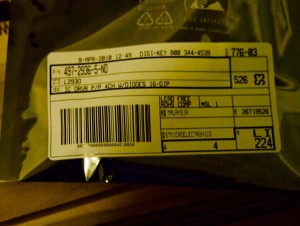
From Adafruit’s forums I figured out what ic’s I need to order (L293). Here is the label on the esd bag.
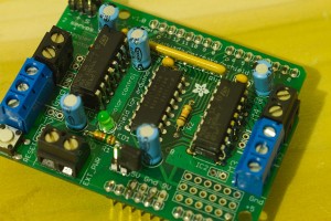
Now all that you need to do is solder them on top of the existing motor driver chips! As strange as it sounds, the theory has been vetted. Each one of those drivers can handle 600mA continuous. By stacking one on top of another they each handle ~600mA and you end up with ~1200mA! The motor shield has two driver ICs mounted on it, they are the two outer ones.
Here is a shot of the board. It is assembled, but it only has one motor driver chip per channel (‘channel’ feels weird there, but you know what I mean)
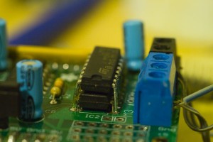
Here is a closeup of one chip stacked on top of the other.

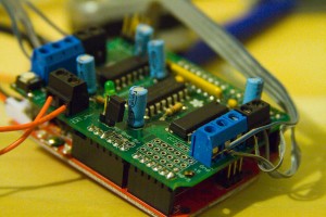
If you look closely on this pic you will notice that I actually soldered it on backwards! That was an incredible pain to unsolder, so be sure to do it right. I had to heat each leg up and then pry it off with a toothpick. There is a little notch on each of the chips. Make sure they are both on the same side.
Due to the tight space this was a really ugly solder job. I ended up putting flux on the outside of the mounted chip, and the inside of the legs of the new chip. I then tinned each of the legs of the new chip and let it cool. Finally I stacked the chips, touched the soldering iron to the outside of the new one and then removed heat and held it briefly in place with a jewelers screwdriver. The springy nature of the legs meant that it was sometimes hard to keep them in contact after removing the heat, but it is doable.
Here is a shot of my very ugly soldering job

If you know that you are going to want the increased current when you order this, then it would make a lot of sense to build the piggyback on the board first. You will be able to access the legs much more easily. This mod enables you to get around 1200mA out of the board. That helps move you into bigger motors. It still might be a good idea to put a fan or a heatsink on it if you plan on taxing the system.


Thanks for this post! Just piggybacked the l293d chips. It was nice to see pictures. Boo ya!
do you know if it is 1200mA peak? I thought it was 1200mA peak before with the 600mA single chip on. Does anyone know what the new peak is? Can I use all four now to power one stepper? I don’t want to fry this bitch.
I think it was 600ma continuous per chip before. Now it ought to be just under 1200mA continuous per chip. On the forums, Lady Ada says that you can wire the chips together, but you have to be extremely careful about turning both chips on and off at the exact time. She even goes so far as to suggest re-writing the driver code to treat them both as the same.
Good luck Brandon!
I think it was 600ma continuous per chip before. Now it ought to be just under 1200mA continuous per pair of chips. On the forums, Lady Ada says that you can wire the chips together, but you have to be extremely careful about turning both chips on and off at the exact time. She even goes so far as to suggest re-writing the driver code to treat them both as the same.
Good luck Brandon!
Thank you for this ! I’ll make a biggy soon because the 754 alone can’t handle two DC motors, need 2 754’s piggyriding =P
Just a word for the people considering this: I still ended up blowing this thing up.
it is a great starter setup, but if you are planning on getting bigger motors, you should really go out and either get a pololu, a big easy driver, or a dedicated cd motor driver.